

The “Internet of Stranger Things” Wall, Part 1 – Introduction and Remote Wiring
Overview
I am a child of the 80s. Raiders of the Lost Ark was the first movie I saw by myself in the movie theater. The original Star Wars trilogy was an obsession. And WarGames is one thing that inspired me more than anything else to become a programmer.
But it was movies like The Goonies that I would watch over and over again because they spoke to me in a language that reflected what it was like to be a kid at that time. They took kids on a grand adventure, while still allowing them to be kids in a way that so few movies can pull off.
So, of course when a friend pointed out the Netflix series Stranger Things, I dove right in, and while sitting down at my PC I binge-watched every episode over a weekend. It had a treatment of 80s childhood that was recognizable, without being a painful cliché. It referenced movies like The Goonies, ET, and The X-Files in a really fun way.
If you haven’t yet watched the series, go ahead and watch it now. This blog post will still be here when you finish up. 🙂
One of the most iconic scenes in the movie is when Winona Ryder, herself a star of some of my favorite 80s and 90s movies, uses an alphabet wall made of Christmas lights to communicate with her son Will, who is stuck in the Upside Down.
While not physically there, Will could still hear her. So, she would ask him a question and he would respond by lighting up the individual Christmas light associated with each letter on the wall. In the show, the alphabet wall takes up one whole wall in her living room.
I won’t go into more detail than that because I don’t want to spoil the show for those who have not yet seen it or for those who didn’t take my advice to stop and watch it now.
Here’s my smaller (approximately 4’ x 4’) version of the alphabet wall as used during my keynote at the TechBash 2016 conference in Pennsylvania:
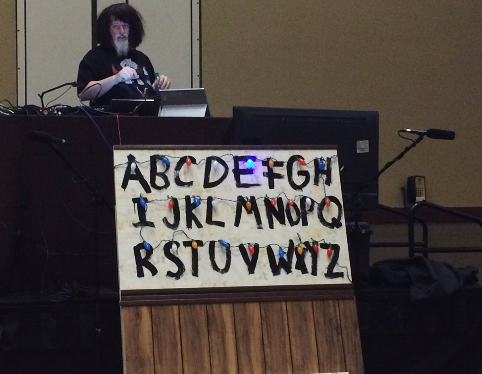
“Will? Will? Are you there?”
In the events I used it in, I put on a wig that sort-of resembled Winona’s frazzled hair in the series (but also made me look like part of a Cure cover band), and had my version of the theme/opening music playing on an Elektron Analog Four synthesizer/sequencer in the background. I then triggered the wall with a question and let it spell out the answer with the Christmas lights on the board.
Here’s a block diagram of the demo structure. You can see it involves a few different pieces, all of which are things I enjoy playing with.
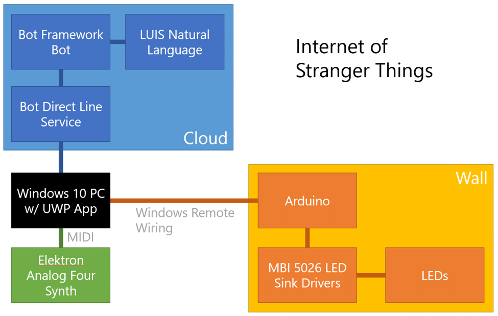
In this three-part series, I’ll describe how I built the wall, what products I used, how I built the app, how I built and communicated with the bot framework-based service, and how I made the music. In the end, you should have enough information to be able to create your own version of the wall. You’ll learn about:
- Windows Remote Wiring
- LCD Sink ICs
- Constructing the Wall
- Wiring the LED Christmas lights
- Adding UWP voice recognition
- Setting up a natural language model in LUIS
- Building a Bot Framework-based bot
- Music and MIDI
- And more
There will be plenty of code and both maker and developer-focused technical details along the way.
This first post will cover:
- Creating the UWP app
- Windows Remote Wiring
- Using the MBI5026 LED sink driver
If you’re unfamiliar with the show or the wall, and want to see a quick online-only version of a Stranger Things alphabet wall you can see one at http://StrangerThingsGIFGenerator.com. Example:
The remainder of the series will be posted this week. Once they are up, you’ll be able to find the other posts here:
- Part 1 – Introduction and Remote Wiring
- Part 2 – Constructing the wall and adding Music
- Part 3 – Adding voice recognition and intelligence (this post)
Creating the basic UWP app
This app is something I used for demonstrating at a couple conferences. As such, it has an event-optimized UI — meaning big text that will show up well even on low contrast projectors. Additionally, it means I need a button to test the board (“Send Alphabet”), test MIDI (“Toggle MIDI”), echo back in case the network is down, and also submit some canned questions in case the network or bot service can’t be reached. When you do live demos, it’s always good to have backups and alternate paths so that a single point of failure doesn’t kill the entire demo. From experience, I can tell you that networks at venues, even speaker and keynote networks, are the single most common killer of cool demos.
This is the UI I put together.
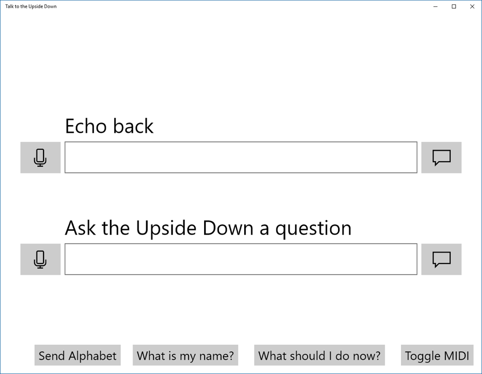
The microphone button starts voice recognition. In case of microphone failure (backups!) I can simply type in the text box — the message icon to the right submits the message. In the case of echo, it simply lights it up on the wall with the text, bypassing the online portion of the demo. In the case of the “Ask a question” field, it sends the message to a Bot Framework bot to be processed.
Despite the technologies I’m using, everything here starts with the standard C#/XAML UWP Blank App template in Visual Studio. I don’t need to use any specific IoT or bot-centric templates for the Windows 10 app.
I am on the latest public SDK version at the time of this post. This is important to note, because the NuGet MIDI library only supports that version (or higher) of the Windows 10 Anniversary Update SDK. (If you need to use an earlier version like 10586, you can compile the library from source.)
I use the Segoe MDL2 Assets font for the icons on the screen. That font is the current Windows standard iconography font. There are a few ways to do this in XAML. In this case, I just set the font and pasted in the correct Unicode value for the icon (you can use Character Map or another app if you wish). One very helpful resource that I use when working with this font is the ModernIcons.io Segoe MDL2 Assets – Cheatsheet site. It gives you the Unicode values in a markup-ready format, making it super easy to use in your XAML or HTML app.
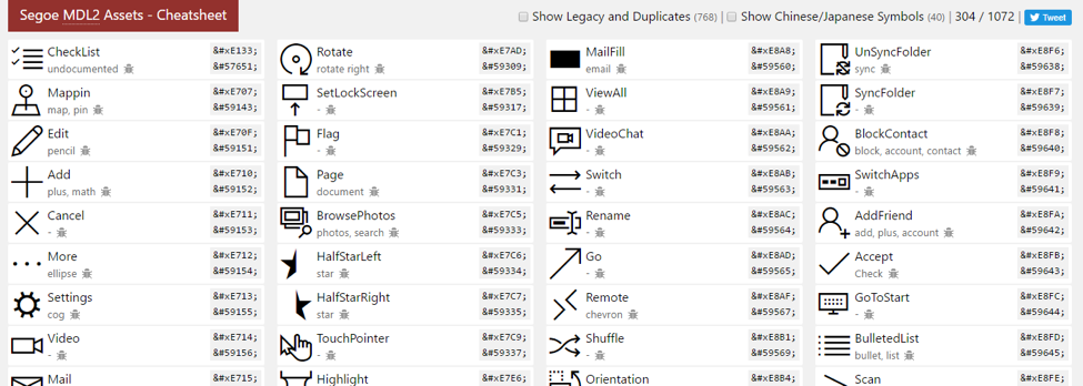
There’s also a free app which you may prefer over the site.
The rest of the UI is standard C# and XAML stuff (I’m not doing anything fancy). In fact, when it comes to program structure you’ll find this demo wanting. Why? When I share this source code, I want you to focus on what’s required to use any of these technologies rather than taking a cognitive hit trying to grok whatever design pattern I used to structure the app. Unless specifically trying to demonstrate a design pattern, I find over-engineered demo apps cumbersome to trod through when looking for a chunk of code to solve a specific problem.
Windows Remote Wiring Basics
When I built this, I wanted to use it as a way to demonstrate how to use Windows Remote Wiring (also called Windows Remote Arduino). Windows Remote Wiring makes it possible to use the IO on an Arduino from a Windows Store app. It does this by connecting to the Arduino through a USB or Bluetooth serial connection, and then using the Firmata protocol (which is itself built on MIDI) to transfer the pin values and other commands back and forth.
Typically used with a PC or phone, you can even use this approach with a Windows 10 IoT Core device and an Arduino. That’s a quick way to add additional IO or other capabilities to an IoT project.
For a primer on Remote Wiring, check the link above, or take a look at this video to learn a bit more about why we decided to make this possible:
https://channel9.msdn.com/events/Build/2015/2-724
Remoting in this way has slower IO than doing the work directly on the Arduino, but as an example this is just fine. If you were going to do something production-ready using this approach, I’d recommend bringing the calls up to a higher level and remote commands (like “Show A”) to the Arduino instead of remoting the pin values and states.
The reason the PC is involved at all is because we need the higher-level capabilities offered by a Windows 10 PC to communicate with the bot, do voice recognition, etc. You could also do these on a higher level IoT Core device like the Intel Joule.
Remote wiring is an excellent way to prototype a solution from the comfort of your PC. It’s also very useful when you’re trying to decide what capabilities you’ll ultimately need in the final target IoT board. The API is very similar to the Windows.Devices.Gpio APIs, so moving to Windows 10 IoT Core when moving to production is not very difficult at all.
For my project, I used a very long USB cable. I didn’t want to mess around with Bluetooth at a live event.
To initialize the Arduino connection in this project, I used this code in my C# standard Windows 10 UWP app:
[code lang=”csharp”]
RemoteDevice _arduino;
UsbSerial _serial;
private const string _vid = "VID_2341";
private const string _pid = "PID_0043";
private void InitializeWiring
{
_serial = new UsbSerial(_vid, _pid);
_arduino = new RemoteDevice(_serial);
_serial.ConnectionEstablished += OnSerialConnectionEstablished;
_serial.begin(57600, SerialConfig.SERIAL_8N1);
}
[/code]
I got the VID and PID from looking in the Device Manager properties for the connected Arduino. Super simple, right? I found everything I needed in our tutorial files and documentation.
The final step for Arduino setup is to set the pin modes. This is done in the handler for the ConnectionEstablished event.
[code lang=”csharp”]
private void OnSerialConnectionEstablished()
{
//_arduino.pinMode(_sdiPin, PinMode.I2C);
_arduino.pinMode(_sdiPin, PinMode.OUTPUT);
_arduino.pinMode(_clockPin, PinMode.OUTPUT);
_arduino.pinMode(_latchPin, PinMode.OUTPUT);
_arduino.pinMode(_outputEnablePin, PinMode.OUTPUT);
_arduino.digitalWrite(_outputEnablePin, PinState.HIGH); // turn off all LEDs
ClearBoard(); // clear out the registers
}
private const UInt32 _clearValue = 0x0;
private async void ClearBoard()
{
// clear it out
await SendUInt32Async(_clearValue, 0);
}
[/code]
The SendUInt32Async method will be explained in a bit. For now, it’s sufficient to know that it is what lights up the LEDs. Now to work on the electronics part of the project.
Arduino connection to the LCD sink ICs
There are a number of good ways to drive the LEDs using everything from specialized drivers to transistors to various types of two dimensional arrays (a 5×6 array would do it, and require 11 IO pins). I decided to make it super simple and dev board-agnostic and use the MBI5026GN LED driver chip, purchased from Evil Mad Scientist. A single MBI5026 will sink current from 16 LEDs. To do a full alphabet of 26 letters, I used two of these.
The MBI5026 is very simple to use. It’s basically a souped-up shift register with above-average constant current sinking abilities. I connected the LED cathodes (negative side) to the pins and the anode (positive side) to positive voltage. To turn on an LED, just send a high value (1) for that pin.
So for 16 pins with pins 0 through 5 and 12 and 15 turned on, that means that we would send a set of high/low values that looks like this:
![]()
The MBI5026 data sheet explains how to pulse the clock signal so it knows when to read each value. There are a couple other pins involved in the transfer, which are also documented in the data sheet.
The IC also includes a pin for shifting out bits that are overflowing from its 16 positions. In this way, you can chain as many of these together as you want. In my case, I chained together two and always passed in 32 bits of data. That’s why I used a UInt32 in the above code.
In this app, I’ll only ever turn on a single LED at a time. So every value sent over will be a single bit turned on with the other thirty-one bits turned off. (This also makes it easier to get away with not worrying about the amp draw from the LEDs.)
To make mapping letters to the 32-bit value easier, I created an array of 32-bit numbers in the app and stored them as the character table for the wall. Although I followed alphabetic order when connecting them, this table approach also supports arbitrary connections of the LEDs as long as you keep alphabetical the actual order for the values in the array.
[code lang=”csharp”]
private UInt32[] _letterTable = new UInt32[]
{
0x80000000, // A 10000000000000000000000000000000 binary
0x40000000, // B 01000000000000000000000000000000
0x20000000, // C 00100000000000000000000000000000
0x10000000, // D …
0x08000000, // E
0x04000000, // F
0x02000000, // G
0x01000000, // H
0x00800000, // I
0x00400000, // J
0x00200000, // K
0x00100000, // L
0x00080000, // M
0x00040000, // N
0x00020000, // O
0x00010000, // P
0x00008000, // Q
0x00004000, // R
0x00002000, // S
0x00001000, // T
0x00000800, // U
0x00000400, // V
0x00000200, // W …
0x00000100, // X 00000000000000000000000100000000
0x00000080, // Y 00000000000000000000000010000000
0x00000040, // Z 00000000000000000000000001000000
};
[/code]
These numbers will be sent to the LED sink ICs, LSB (Least Significant Bit) first. In the case of the letter A, that means the bit to turn on the letter A will be the very last bit sent over in the message. That bit maps to the first pin on the first IC.
LEDs require resistors to limit current and keep from burning out. There are a number of scientifically valid approaches to testing the LED lights and figuring out which resistor size to use. I didn’t use any of them, and instead opted to burn out LEDs until I found a reasonable value. 🙂
In reality, with the low voltage we’re using, you can get close using any online resistor value calculator and the default values. We’re not trying to maximize output here and the values would normally be different from color to color (especially blue and white vs. orange and red), in any case. A few hundred ohms works well enough.
Do note that the way the MBI5026 handles the resistor and sets the constant current is slightly different from what you might normally use. One resister is shared for all 16 LEDs and the driver is a constant current driver. The formula is given on page 9 of the datasheet.
IOUT = (VR-EXT / Rext ) x 15
But again, we’re only lighting one LED at a time and we’re not looking to maximize performance or brightness here. Additionally, we’re not using 16 LEDs at once. And, as said above, we also don’t know the actual forward current or forward voltage of the LEDs we’re using. If you want to be completely correct, you could have a different sink driver for each unique LED color, figure out the forward voltage and the correct resistor value, and then plug that in to the appropriate driver.
With that information at hand, it’s time to wire up the breadboard. Assuming I didn’t forget any, here’s the list of all the connections.
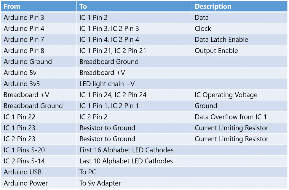
Or if you prefer something more visual:
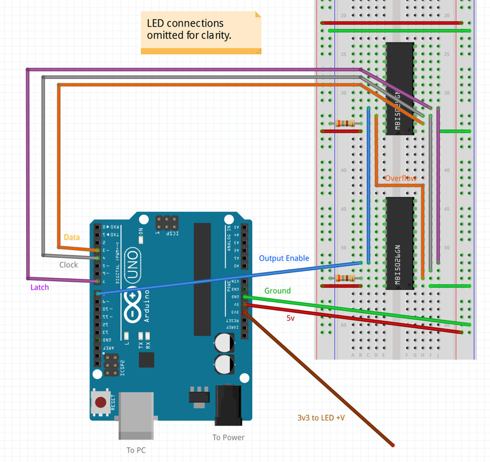
I handled the wiring in two stages. In stage one, I wired the MBI5026 breadboard to the individual posts for each letter. This let me do all that fiddly work at my desk instead of directly on the wall. I used simple construction screws (which I had tested for conductivity) as posts to wire to.
You can see the result here, mounted on the back of the wall.
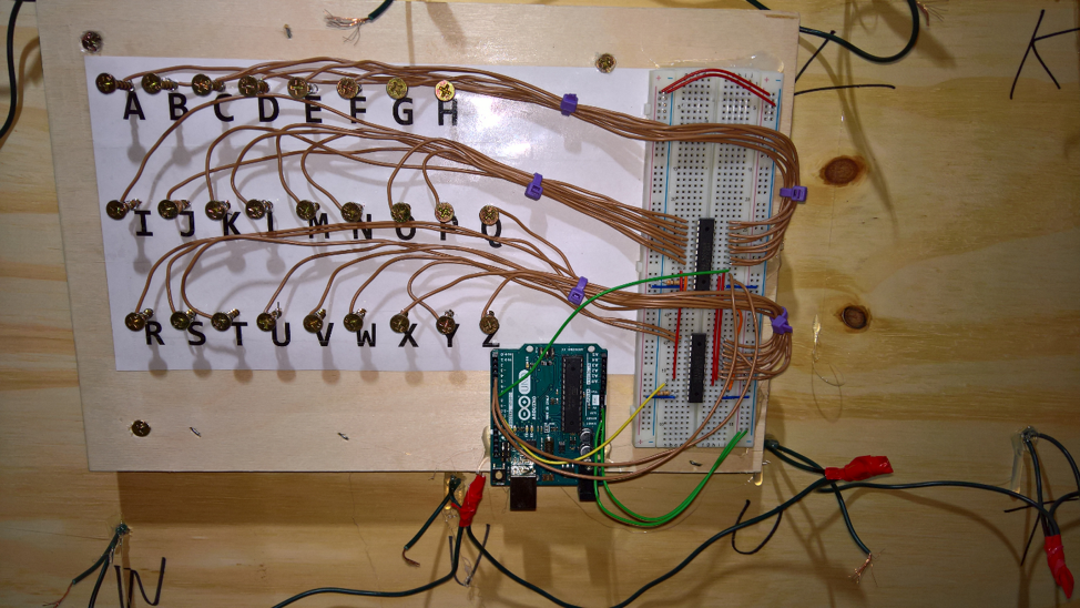
You can see the individual brown wires going from each of the output pins on the pair of MBI5026 ICs directly to the letter posts. I simply wrapped the wire around the post; there is no solder or hot glue involved there. If you decide to solder the wires, use caution and be advised that the screws will sink a lot of the heat, likely to end up scorching the paper label and burning down all your hard work. The wire wrapped approach is easier and also easily repaired. It also avoids fire. Fire = bad.
The board I put everything on ended up being a bit large to fit between the rows on the back of the wall, so I took the whole thing over to the table saw. I’m the first person I know to take an Arduino, breadboard and wired circuit, and run it across a saw. It survived. 🙂

In the Windows app, I wanted to make sure the code would allow taking an arbitrary string as input and would light up the LEDs in the right order. First, the code that processes the string:
[code lang=”csharp”]
public async Task RenderTextAsync(string message,
int onDurationMs = 500, int delayMs = 0,
int whitespacePauseMs = 500)
{
message = message.ToUpper().Trim();
byte[] asciiValues = Encoding.ASCII.GetBytes(message);
int asciiA = Encoding.ASCII.GetBytes("A")[0];
for (int i = 0; i < message.Length; i++)
{
char ch = message[i];
if (char.IsWhiteSpace(ch))
{
// pause
if (whitespacePauseMs > 0)
await Task.Delay(whitespacePauseMs);
}
else if (char.IsLetter(ch))
{
byte val = asciiValues[i];
int ledIndex = val – asciiA;
UInt32 bitmap = _letterTable[ledIndex];
// send the letter
await SendUInt32Async(bitmap, onDurationMs);
// clear it out
await SendUInt32Async(_clearValue, 0);
if (delayMs > 0)
await Task.Delay(delayMs);
}
else
{
// unsupported character. Ignore
}
}
}
[/code]
The code first gets the ASCII value for each character in the string. Then, for each character in the string, it checks to see if it’s whitespace or a letter. If neither, it is ignored. If whitespace, we delay for a specified period of time. If a letter, we look up the appropriate letter 32-bit value (a bitmap with a single bit turned on), and then send that bitmap to the LEDs, LSB first.
The code to send the 32-bit map is shown here:
[code lang=”csharp”]
private const int _latchPin = 7; // LE
private const int _outputEnablePin = 8; // OE
private const int _sdiPin = 3; // SDI
private const int _clockPin = 4; // CLK
// send 32 bits out by bit-banging them with a software clock
private async Task SendUInt32Async(UInt32 bitmap, int outputDurationMs)
{
for (int i = 0; i < 32; i++)
{
// clock low
_arduino.digitalWrite(_clockPin, PinState.LOW);
// get the next bit to send
var b = bitmap & 0x01;
if (b > 0)
{
// send 1 value
_arduino.digitalWrite(_sdiPin, PinState.HIGH);
}
else
{
// send 0 value
_arduino.digitalWrite(_sdiPin, PinState.LOW);
}
// clock high
_arduino.digitalWrite(_clockPin, PinState.HIGH);
await Task.Delay(1); // this is an enormous amount of time,
// of course. There are faster timers/delays
// you can use.
// shift the bitmap to prep for getting the next bit
bitmap >>= 1;
}
// latch
_arduino.digitalWrite(_latchPin, PinState.HIGH);
await Task.Delay(1);
_arduino.digitalWrite(_latchPin, PinState.LOW);
// turn on LEDs
_arduino.digitalWrite(_outputEnablePin, PinState.LOW);
// keep the LEDs on for the specified duration
if (outputDurationMs > 0)
await Task.Delay(outputDurationMs);
// turn the LEDs off
_arduino.digitalWrite(_outputEnablePin, PinState.HIGH);
}
[/code]
This is bit-banging a shift register over USB, to an Arduino. No, it’s not fast, but it doesn’t matter at all for our use here.
The MBI5026 Data Sheet includes the timing diagram I used when figuring out how to send the clock signals and data. Note that the actual period of these clock pulses isn’t important, it’s the relative timing/order of the signals that counts. The MBI5026 can be clocked at up to 25MHz.

Using that information, I was able to prototype using regular old LEDs on a breadboard. I didn’t do all 26, but I did a couple at the beginning and a couple at the end to ensure I didn’t have any off-by-one errors or similar.
Next, I needed to scale it up to a real wall. We’ll cover that in the next post, before we finish with some speech recognition and natural language processing.
Resources
- My stranger things repo on GitHub
- Get started with UWP and Windows 10
- Windows Remote Wiring
- MBI5026GN LED Driver Chip @ Evil Mad Scientist
- Windows 10 IoT Core
- Netflix series: Stranger Things
Questions or comments? Have your own version of the wall, or used the technology described here to help rid the universe of evil? Post below and follow me on twitter @pete_brown
Most of all, thanks for reading!