Never before has it been so easy to turn an idea into a physical object. The intersection of powerful 3D modeling tools and new technologies like 3D printing has created new opportunities and have changed the way people think about design and manufacturing. With Windows 8.1, 3D printing is built-in, which makes it even easier and more seamless to print to your 3D printer.
In this post I’ll talk about using SolidWorks 2014 CAD software to design a part for 3D printing based on a project I just completed. SolidWorks is a Windows-exclusive application that is considered the “industry standard” 3D modeling tool for many design, simulation, and analysis engineering applications. The 2014 version of SolidWorks was just released this month, and is packed with great features and capabilities.
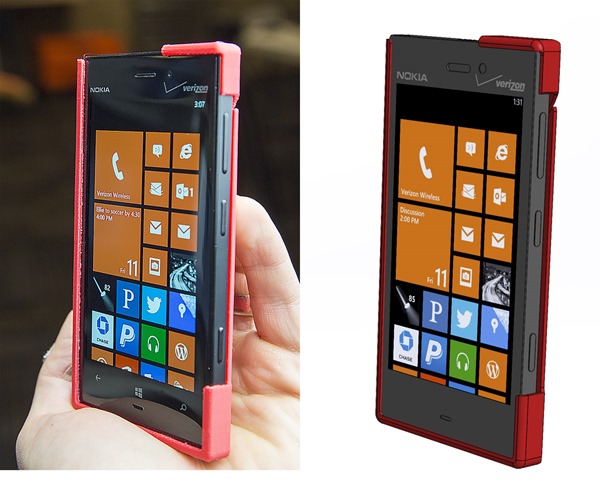
Finished 3D printed phone case (left) and 3D assembly in SolidWorks (right) – click/tap to enlarge
Designing a Phone Case with SolidWorks
So you just bought a 3D printer. What’s the first thing you’re going to do when you get it? If you’re like me, you’ll want to print out a case for your phone. It’s almost a rite of passage for 3D printer owners, like writing a “Hello World” app when you start programming. As a Mechanical Engineer, I was just as excited to design and print the phone case as I was to use it.
While there are many ways to approach the design of a phone case, I decided on a simple approach: first create a 3D model of my Nokia Lumia 928, and then build the case around it.
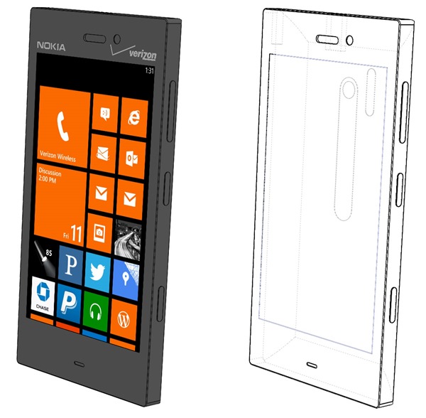
Solid model of my Nokia 928 phone fully rendered (left) and with hidden lines shown (right) click/tap to enlarge
Once I had created the model of the phone, I created a “skin” around the phone by using a feature in SolidWorks called “surface offset”. This literally allows the designer to “push out” a surface and make a new surface that results in a consistent offset thickness between the two surfaces.
Left: phone surface (blue) and offset surface (yellow), Middle: outer surface of case (red), Right: inner and outer surfaces with hidden lines shown – click/tap to enlarge
With the inner surface (phone) and outer surface (case) geometry completed it is then possible to “subtract” the phone volume from the overall volume by using the “combine” command in SolidWorks. This leaves the constant-thickness shell which can then be cut accordingly to leave only the parts of the case that are needed for protection and/or appearance. The completed case part fits the phone exactly and cutouts are placed precisely in relation to the display, buttons, camera, speaker, and other features.
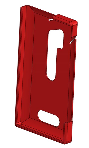
Nokia 928 phone case design in SolidWorks 2014 – .050” shell thickness – click/tap to enlarge
Special Considerations for 3D Printing
If I had a 3D printer that could print this part using rubber-like materials, this design would likely work great as-is. For this project I used a MakerBot Replicator 2 Desktop 3D Printer that prints using PLA plastic. Fused filament 3D printers are extremely powerful prototyping and manufacturing tools that require special knowledge about how they work in order to create optimized parts with them. One of the things that I learned early on using these kinds of printers is how tolerances are not absolute. Fused filament printed part surfaces have a “texture” that adds to the surfaces specified by the corresponding 3D model. This extra texture is a function of the printer being used, the material used for printing, and the print settings used. With the MakerBot Replicator 2 I found that when using “Standard” print settings this texture accounts for about .010” – .020” of extra surface texture. If you don’t account for this surface texture, the phone won’t fit in the case!
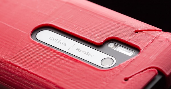
Tiny ridges follow the path of the extruder when fused filament printing is performed – MakerBot Replicator 2 texture shown here using “Standard” print settings
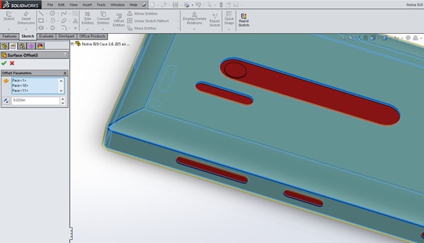
My solution to account for this surface texture was to add an extra surface offset (inflation of the surface of the phone model) to create an “air gap” between the phone solid model and the case solid model. Since SolidWorks is a parametric solid modeling application, this parameter (air gap thickness) can be easily tweaked at a later time by adjusting the surface offset value. This is a very powerful capability! In SolidWorks you can even drive parameters from an external data source like an Excel spreadsheet. This Excel-driven approach would be a great way to fine-tune a phone case solid model for different materials, printers, and print settings.
Creating a .025” surface offset to account for air gap and surface texture of 3D print in SolidWorks 2014 – click/tap to enlarge
There are some additional considerations that you should evaluate when designing for 3D printing:
- Overhangs and supports: Since 3D printers build up parts in layers, you have to think about how the material will be built up. If you have overhangs (material with nothing underneath to support it) you may be able to use in-place printed supports to overcome issues with spans and sagging material while printing. The general rule of thumb is called the “45 degree rule”. If the overhang slopes more than 45 degrees (more horizontal than vertical), then you’ll need to use supports when printing.
- Warping and shrinkage: Some materials like ABS plastic will shrink as they cool during and after printing. This can cause great internal stresses in your printed part, separations, and warping of the model. You can mitigate some of these issues by using a heated platform (if printing ABS plastic), printing on a raft (printed support platform for part), carefully adjusting infill options (internal printed structure of part), and reading articles online that discuss these issues and corresponding mitigations.
- Material Properties: There are now many types of filaments (plastic string) that are used by 3D printers. Each of the corresponding materials has different properties including strength, thermal expansion coefficient, elasticity, and melting point. You’ll need to figure out what printer settings and design tweaks are needed in order to optimize printing results for the material you plan to use.
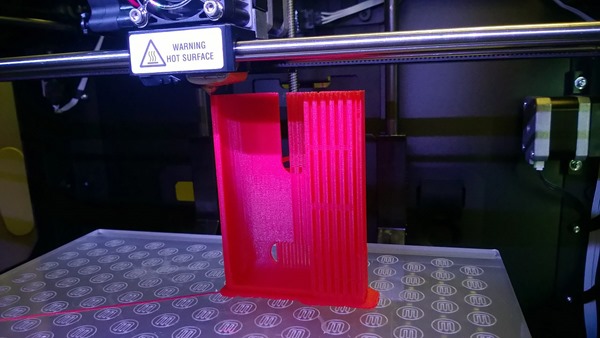
Nokia 928 case printing on MakerBot Replicator 2 with raft (between case and platform) and supports (vertical columns of material) – click/tap to enlarge
Iterative Design and Manufacturing
With the combination of parameter-driven 3D modeling and 3D printing it’s possible to refine designs in a fraction of the time it takes without these capabilities. For the phone case design scenario, you can ideally refine a design in about 3 iterations:
- Iteration 1: Print with default gaps/tolerances (can be zero). Measure actual internal dimensions of phone case shell, calculate part adjustments, and update part.
- Iteration 2: Print with adjusted tolerances. Try parts for fit, take measurements as needed, update part.
- Iteration 3: Print “final” part and test.
In addition to getting the tolerances right for this phone case, I also used iterative design to get the “snap over” case corner just right. It took a few iterations to optimize the “positive locking action” of the corner profile, as well as the grooves and stress relief holes that allow the corner to flex without fatiguing the plastic.
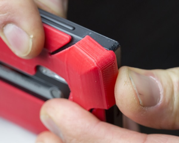
Snap! With the corner design optimized, the case effectively retains the phone and makes it easy to install and remove – click/tap to enlarge
If you have extensive experience with the printing method and equipment you are using, the number of iterations is going to be less. If you’re just getting started, you’ll likely have a lot more iterations than what’s shown above. It’s quite satisfying to arrive at an optimized design for your creation.
You may be wondering what it costs to print out a phone case like this. I wondered this as well. Here’s a quick calculation of the per-print cost (case material only, raft and supports not included):
- PLA filament: $48.00 / kg
- Phone case: .02 kg
- Cost per print: $0.96
At under a buck in finished material per print, you can afford to iterate plenty!
Want to print out a Nokia 928 case of your own? You’re in luck! You can download this Nokia 928 phone case from Thingiverse here:
Nokia Lumia 928 Phone Case by gavingear
Thousands of Possibilities
Now that I have solid models for this phone and case, I can easily extend and adapt this phone case design for other applications. I’m already thinking about how to design other accessories for my Nokia 928 including a video shooting fixture with hand grips, various tripod and mount adapters, and a car dock with integrated wireless charging. It’s all just an extension of my existing design work. The big question is what to do next!
Professional-Grade Tools in SolidWorks
This phone case project really just scratches the surface of what’s possible with SolidWorks 2014. Since SolidWorks makes extensive use of GPU acceleration, you can buy or build a Windows system that can manipulate huge models with fine detail and photo-realistic rendering on ultra-high resolution displays.
SolidWorks also has a ton of powerful and advanced features including:
- SolidWorks Simulation design validation
- SolidWorks Motion prototyping and motion simulation
- SolidWorks Flow Simulation fluid dynamics modeling
- SolidWorks Simulation Premium Finite Element Analysis (FEA)
- SolidWorks Sustainability environmental impact analysis
SolidWorks also offers some great specialty design tools including SolidWorks Routing, SolidWorks Electrical, and SolidWorks Plastics. If you are looking for professional-grade 3D modeling and analysis tools, check out SolidWorks!
Future note: Dassault Systemes and Microsoft are working together to implement Windows 8.1 native 3D printing support in SolidWorks. An early beta of Solidworks 3D printing integration for Windows 8.1 was shown at Maker Faire 2013 in NYC. Stay tuned here on the Extreme Windows Blog for more information!
Find me on Twitter HERE.

